


Engine
December 2008. Original Volvo Penta MD2B (25 h.p.) with MS reverse gear (reduction ratio 1.91:1)
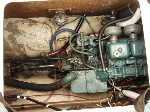
Here is a picture of the original diesel. We were able to start the engine with a help of the ether spray (the weather was quite cold that day). The former owner claimed that it had been overhauled last year and the transmission had been rebuilt. The wiring harness was waiting for a short circuit and a fire in my opinion.
I am thinking of replacing it with a new Volvo Penta D1-30 with MS15L transmission (reduction ratio 2.63/2.96) or Yanmar 3YM20 with a KM2P-1 transmission (reduction ratio 3.22/3.06 or 2.62/3.06) (fwd/rvs).
March 2009. New Yanmar 3YM30 engine
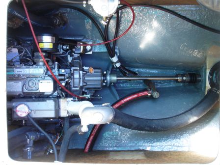
Niemiec Marine repowered Moowind with the new little 30hp Yanmar. It is shorter than Volvo but fattier. Its port side sits very close to the cockpit wall. I would need to remove an alternator in order to get to a starter, for example.
Prop and shaft
A propeller shaft alignment was a major concern because the original Volvo had the shaft positioned below the engine mounts plane and Yanmar has it above by about an inch or so. Hence, the engine must sit lower on its bed. Redoing the bed liners by cutting the embedded metal rails out of the molded fibreglass, and then trimming the mold and glassing in the new metal plates would have been a major expensive refit. Therefore, the new spiffy tall Yanmar mounts were replaced with not so shinny old style short mounts. The matter was of course, not in their brightness but in a weight distribution and a vibration compensation. The new Yanmar has two 150 kg mounts on one diagonal and two 75 kg mounts on the other diagonal. The old style mounts are designed to support equal weight. I wonder if I will be able to detect an increased vibration level because of that?
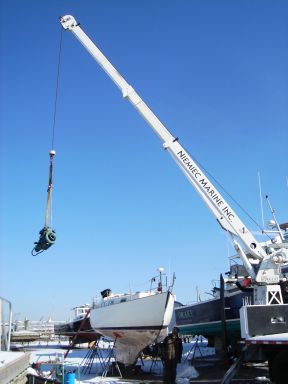
I had prepared the old Volvo for removal by disconnecting all wires, hoses and a shaft coupler. Next morning after the shrink-wrap was cut, the engine did not want to go through its hatch. Chris from Niemiec Marine had to also remove an exhaust manifold and an alternator and then tilt the engine almost vertically with a pulley.
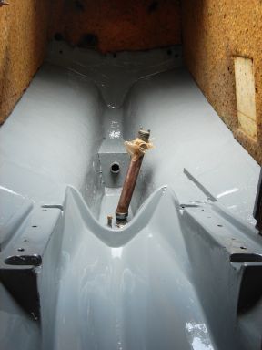
Once the engine was out, I cleaned its compartment and painted with two coats of Interlux bilge enamel. Thanks god the weather was warm and dry over this first weekend in March for a paint to set properly. I also repaired the hole in a cockpit floor made for the Edson pedestal that I had discarded to make more room in the cockpit.
From contacting multiple marines, I knew that I couldn't get away with keeping the original shaft and prop. The shaft would be too short for Yanmar and the prop would spin in the wrong direction! Moreover, the prop size and pitch should match the new engine's RPM and the transmission gear's reduction ratio. Niemiec used some software to calculate the the prop and came up with 14R10.
The cutless bearing was worn out and I wanted to have dripless shaft seal instead of a traditional stuffing box. Niemiec suggested to use a mechanical shaft seal known as PSS. The original bearing was cut along its length for easy removal from the stern tube. The new Johnson cutless bearing BALE (1"x1 1/2"x4") made by Duramax Marine was compression installed and secured with two set screws on the stern tube outside the hull. It turned out to be half inch longer than the tube, so the excess was cut out.
From Cadler's book I understand that mechanical seals if fail result in rapid flooding but otherwise are perfect and can tolerate shaft misalignment, shaft defects and require no maintenance besides replacing a rubber compression sleeve every five years or so and a couple of o-rings. They have a nipple for optional water lubrication, which is mostly useful on power boats due to high shaft RPM when water can be sucked out of the stern tube during an acceleration.
The new shaft was measured and sent out for cutting and keying. What was a surprise when it came back cut a quarter inch shorter than measured! Now what? Through it away and order another one? It would be an expense for Niemiec Marine, probably. One idea was to use a drive saver that is a strong rubber ring that sits in between an engine and a shaft. No, that didn't work because the drive saver was too sick (1" instead of needed 1/4") What worked for the marine and made me a bit unhappy was cutting out 1/4" of the cutless bearing along with the stern tube.
The engine short mixing elbow was replaced with a tall one. Niemiec did the job, it was part of their repowering project. It connects to a water lift muffler.
Fuel system
I replaced the fuel copper tubing with the fuel hoses inside diameter 5/16" and Chris from Niemiec Marine fabricated two new fittings to accept them. He also had to cut two new stainless pipes for the fuel supply and return lines that go inside the tank to replace the original copper ones. Volvo engine did not have the return line but the tank had a line connected to a manual pump for removing water from its bottom. This now became the return line and the pump was discarded. It had been broken anyway.
The fuel filling hose was made of water tubing. The deck fitting was unusual size 1 1/4", likely metric, the same as the other end on the tank. I had to buy the entire hose box, 12 feet, because of non-standard size instead of necessary 8 feet. Nobody wanted to cut it.
Yanmar came with its own water separation filter Racor 230R. I just needed to mount it. I also added the fuel shut-off valve ahead of the filter.
I have also replaced the tank's vent hose that goes to a pushpit's pipe end below the deck. Not sure if this is the right way to do because water can get in.
Cooling and exhaust systems
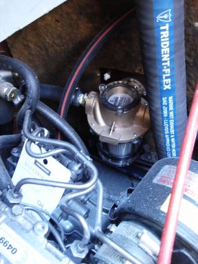
I plumbed the engine's raw water intake to a new Groco bronze ball valve screwed to a new through-hull with a strainer. Another strainer made by Groco and looking similar to a fuel water separator, is seated in-line and is accessible for a periodic cleaning through a companion way's top removable step.
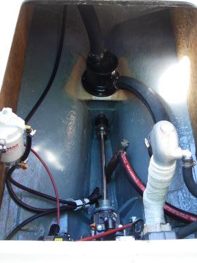
I installed the vented loop between the engine raw water exit and the exhaust elbow mixer, which goes to a fibreglass water lift muffler that I mounted on a glazed plastic lumber platform behind and above the PSS. From the muffler the same 2" heavy-duty exhaust hose makes a loop and goes to a starboard side through-hull, which also had to be replaced because of its size.
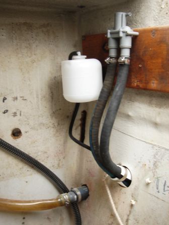
I put the coolant expansion tank in the cockpit locker, next to the raw water vented loop.
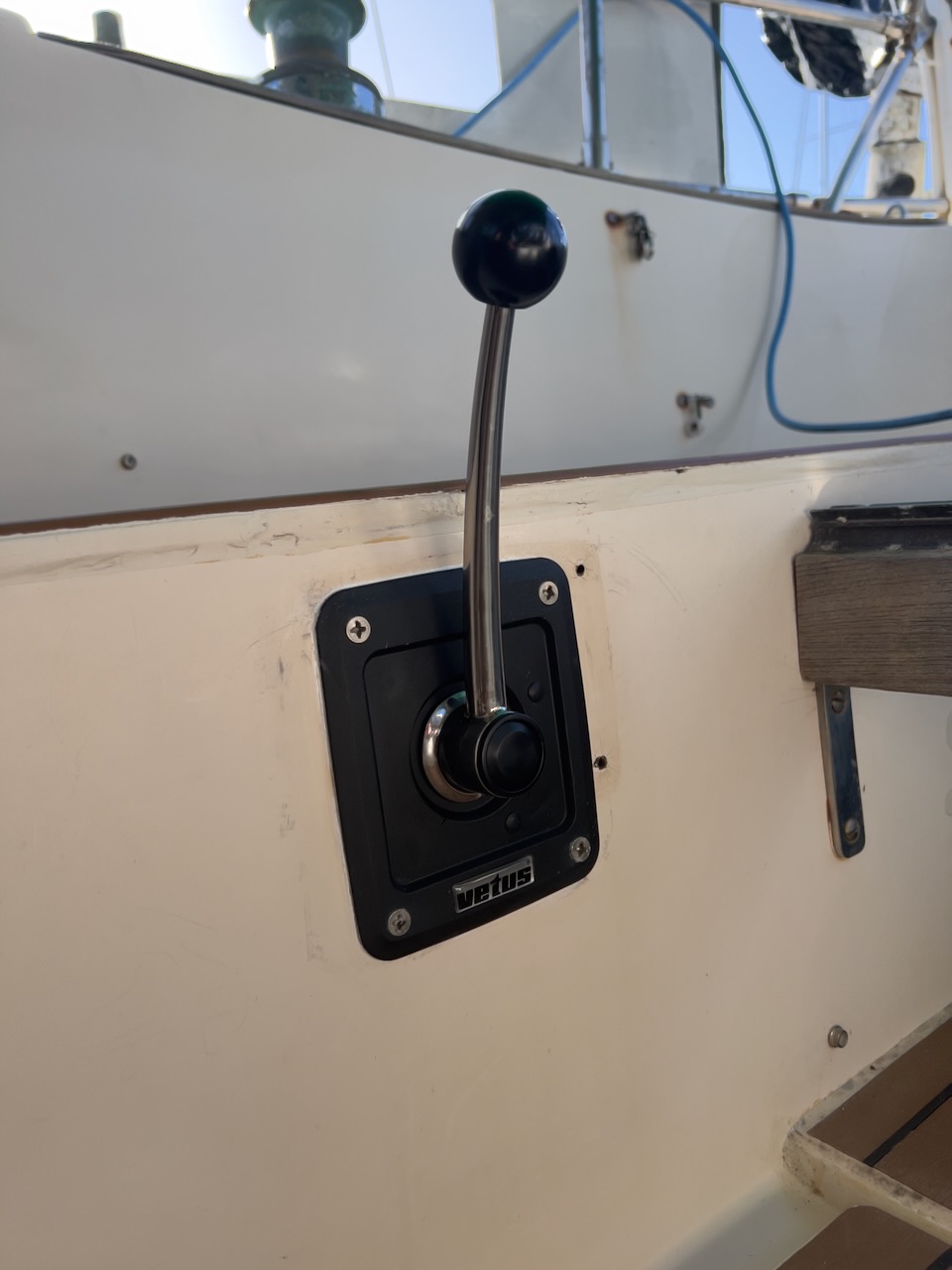
Shifter and throttle
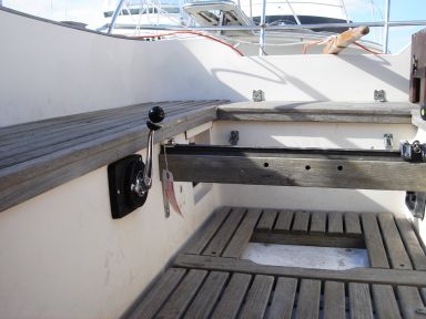
The original Volvo engine had its shifter and throttle on the Edson pedestal. Since the pedestal is gone, I had to order a new shifter and a throttle. I decided to go with a single lever one for safety and convenience reasons.
The mechanism is fully adjustable for right/left hand and for push/pull gear/throttle operations. It can also be oriented to accommodate the cable incoming direction: forward or aft. It has a safety switch that prevents starting an engine in gear. The throttle can be disengaged from the gear by pulling out a handle.
August 2010. Niemiec cheated!
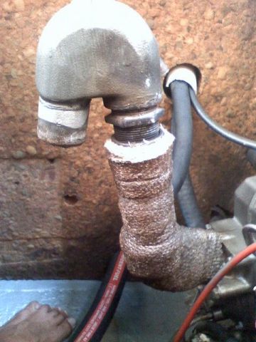
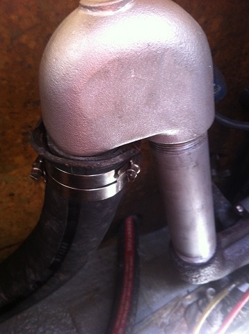
It was the second year of cruising in the Caribbean when the exhaust mixing elbow just fell off! It got loose a few months after the Niemiec completed their repowering project. As you know, they installed a riser in between the cylinder block and the mixing elbow. The riser did not have the matching thread, so Niemiec just ground off the threads of the cylinder block and the elbow and insulated the entire assembly with the tape, most likely to hide their cheating. When it got loose, I just put two clamps around the insulation tape but it did not last long. I was in St. Lucia when it completely fell off. Luckilly, I was idling at the anchorage in Rodney Bay and did not flood the engine.
I sent Niemiec Marine two emails and received no response. This tells me that those guys are not interested in keeping good relations with their customer who paid them quite a lot of money.
This is the third fault made by Niemiec Marine that I discovered so far. The other two were the rudder fairing that also fell off a month after the job had been done and the bilge pump and the switch, both got loose because there were no washers used, just the machine crews.
I had to fix it myself with what I could find in Rodney Bay area on St. Lucia. Not much, I should say.
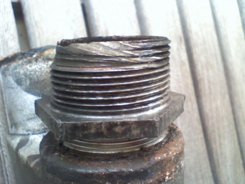
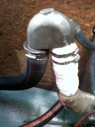
I had to further tune the thread on the exhaust elbow with a file to better match the one on the riser. They have 1/16" difference, by the way. Then I purchased new fibreglass insulating tape and epoxy putty suitable for up to 150° C. This of course may be not enough when the engine is running on high RPM. I also embedded two clamps in the putty, just in case it fails, the elbow will not fall off right away. I tested it on low 1800 rpm and I could still touch the riser with a bare hand. I applied putty in the evening and started the motor next day to heat treat the epoxy. It was supposed to cure to the product that could have withstood even higher temperature. I hope it will.
As a side note, while searching the internet for a fix to my problem, I found that the exhaust riser did corrode and was supposed to be replaced every four years or so. Well, if my new connection last for another three years, I'd be happy.
October 2011. Lip-seal failure on a sea-water pump
I was on my way from Spain to Gibraltar and just left the fuel station in Cartagena when I heard no sound of water spitted through the exhaust. The sea-water leakage from the pump caused the complete damage to belt. If it were unnoticed, the engine would die of overheating. I was lucky that I had a spare belt and in Gibraltar I was able to get the new lip-seal.
November 2012. The second primary fuel filter.
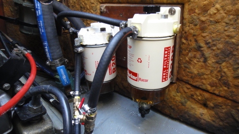
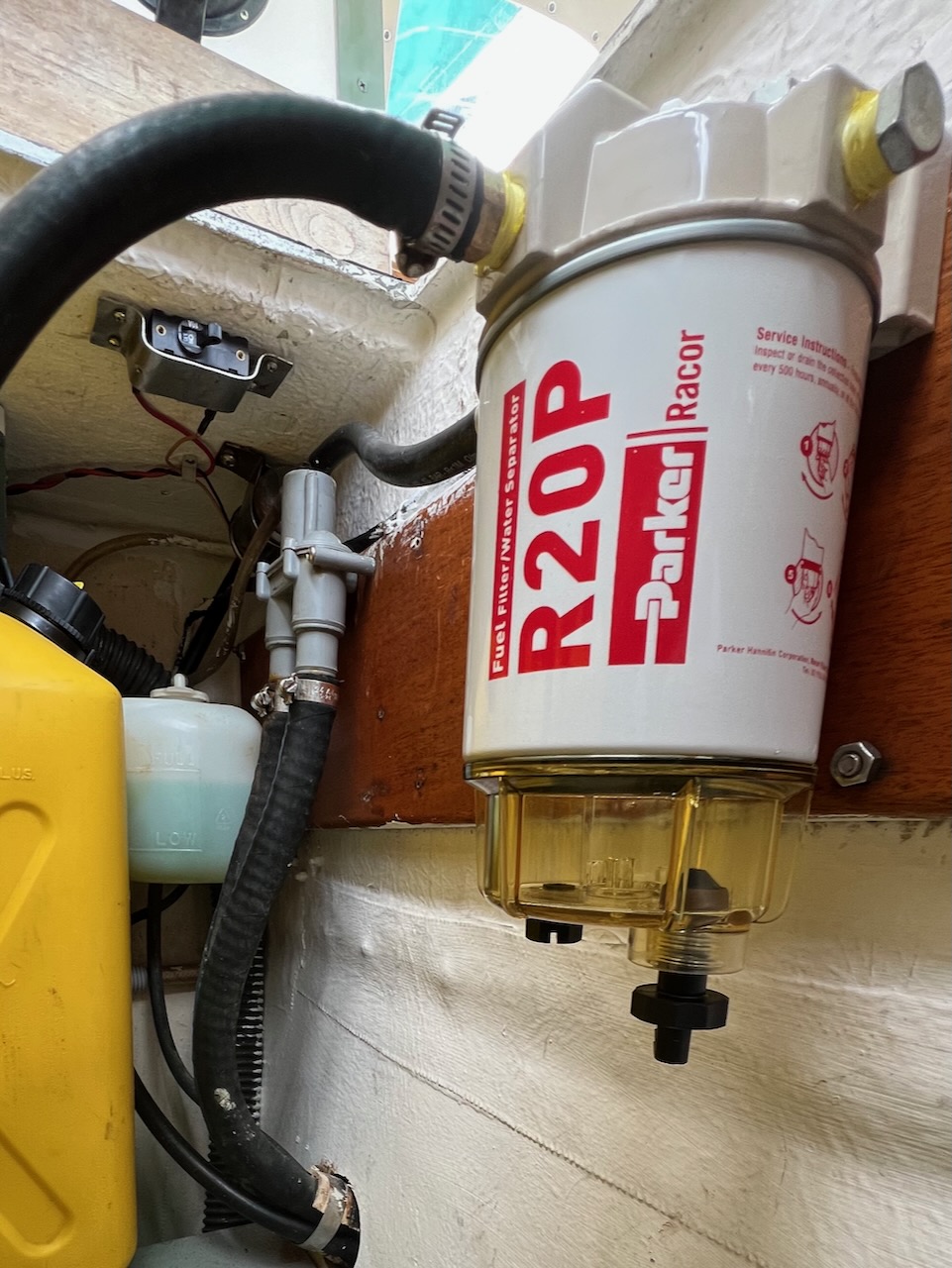
Fuel contamination is apparently such a huge problem in tropics that having a second ready-to-go fuel filter in place is a must! So I added two tees, two valves and another Racor R20P fuel assembly. Now if the first filter gets clogged, switching to the second one will take just a few seconds rather than 30 to 40 minutes - that what it takes to replace a filter in the ocean and it is quite a messy job to do when it's rough there.
November 2012. New bearings and lip-seal for sea-water pump.
At the same time I had to replace not just the lip-seal but also the bearings for the sea-water pump. I got a spare pump because in an emergency its not easy to replace them.
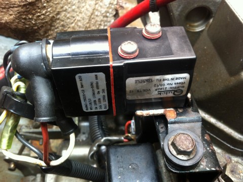
June 2014. New starter solenoid
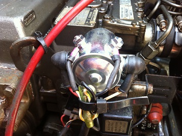
Genuine Hitachi relay failed not far from Faial (Azores) in my third Atlantic crossing. There with a difficulty I was able to find similar model, Cargo, made in China starter solenoid. It was bigger than mine, which was actually good and it had the mounting holes that matched the Yanmar engine. I paid 33 euros for it, not cheap. I had to change the terminals of the triggering wires because they were too small and with a round file slightly enlarge the terminals of the starter wires.
October 2014. It failed again!
The Chinese relay did not last long. In 4 months I had to replace it again! In Gibtaltor it cost me 72 euros! It was different one, made in Italy rather than China. Will see how long it lasts.
October 2015. New mixing elbow and riser pipe
I wrote in my sailing log in July of 2016 that Yanmar lost its RPM due to the clogged mixing elbow.
Yanmar recommends cleaning it every year but I only did it once after the first year. It was more or less clean. Because the riser pipe was not made correctly, I had hard time disassembling the whole thing (see above).
People say that the mixing elbow should be replaced every five years because of corrosion. 7 years passed but the elbow was still strong without any signs of forming holes. I had to hit it very hard with a hammer when I was cleaning it in July. I wanted to solve the cleaning problem though and along with a new mixing elbow I ordered a new riser pipe. The later is somewhat special in a sense that it has different concentric threads on its ends and hence, it is not that easy or even possible to make them with ordinary tools.
Now everything is back in order. I decided to not thermoinsulate the riser pipe in order to reduce corrosion.
As it turned out in 2023, it was not possible to take apart the mixing elbow, the riser pipe and the exhaust manifold. They got welded together by a corrosion. The pipe was a carbon still. No wonder that In a presence of sea water it got stuck. Now all three parts must be replaced as a whole. Cleaning the elbow becomes problematic as well. In May 2023 I ordered all these parts including a gasket and kept them on board as spares.
2020. Auckland. Engine ventilation system
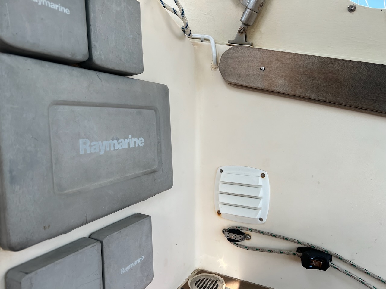
The engine compartment ventilation should have been made by Hallberg-Rassy. I should have made it when I purchased the boat but instead I did it more than 10 years later. I bought a Chinese made engine blower, which came with 2 fans, a duct and two grilles.
The blower is very noisy; therefore, I run it on a schedule for 5 minutes every hour during daytime. It is controlled by Raspberry Pi via WiFi-enabled relay. See Electronics page for more info.
May 2023. Auckland. New engine mounts, shaft, cutless bearing, PSS shaft seal, electrical panel, throttle/gear shifter
Before sailing offshore to finish my circumnavigation, I replaced a few parts on and around the engine.
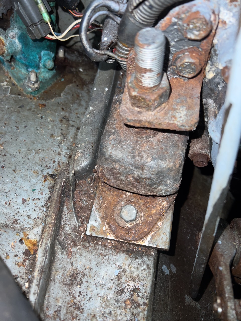
Carbon steel engine mounts corroded badly. I was nervous about them. So I was able to find an exact same model Metalastik Cushyfloat 55 in Auckland. The studs come separately as there are different ones. They are all made of carbon steel. My studs were stepped from 18 to 20 mm meaning that the part that goes into engine brackets has larger diameter (20 mm) than the part that goes into the mount (18 mm). These studs were not available locally. Instead of ordering them, I bought stainless 18 mm studs without a step with stainless washers and nuts. I brought them to a welder to weld a bottom nut to the stud to mimic the original ones. Unstepped studs mean that they will be a bit lose in the engine brackets (a gap of 1 mm). I hoped that it wouldn't be a matter if well tightened.
To replace the mounts, me and my friend Anton raised the engine with two 4:1 fiddle block assemblies that are used for mainsail sheets or a boom vang.
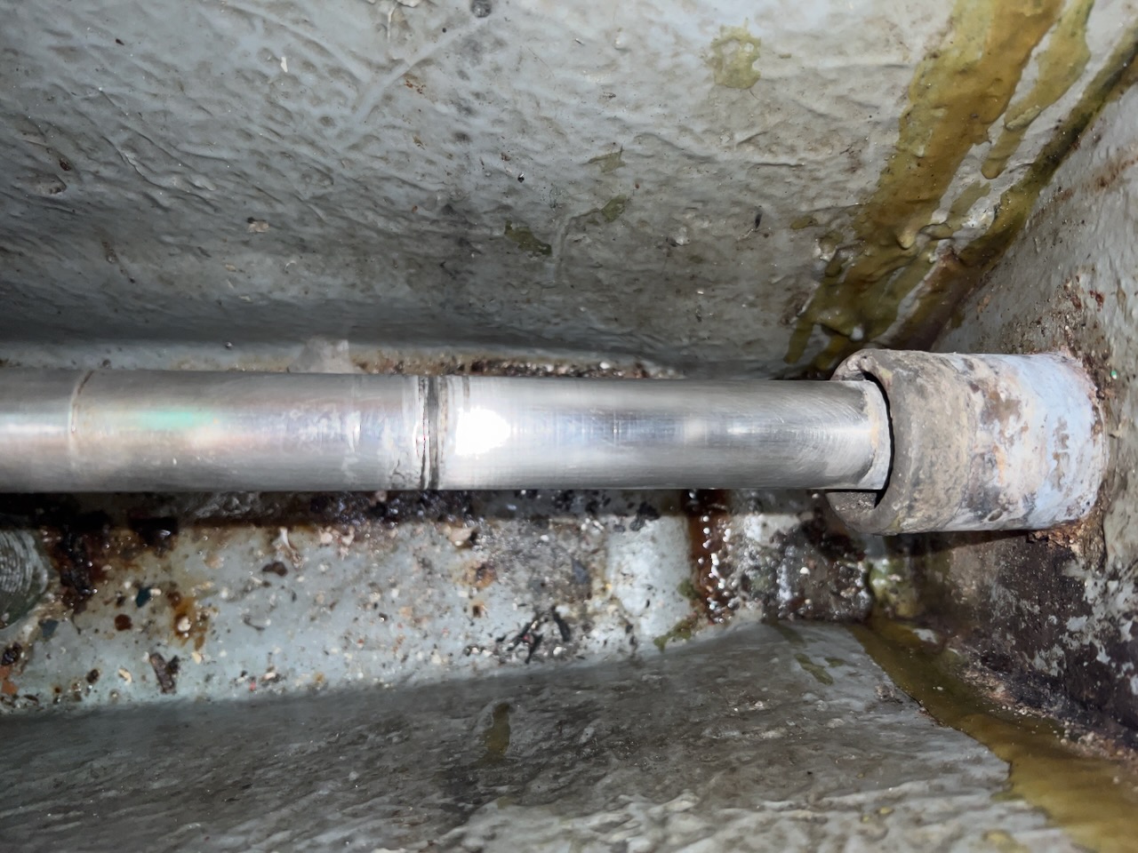
I found a quite deep grove developed on my shaft just behind the PSS shaft seal where the shaft comes into contact with sea water. I suspect that this grove was caused by the stray current corrosion, which cannot be prevented with a zinc anode, which I did not have by the way. This type of corrosion is the result of a poor design - a single wire electric system of an engine where the ground wire is basically the same as the neutral one - a body of an engine! In other words, any excess currents resulting from a leakage from poorly made appliances such as one of my Chinese soldering guns or from defective systems such as a stator of my windgenerator.
All these currents go to seawater (the ground) through the shaft rapidly corroding it. I had to replace the shaft. At the same time I found that cutless bearing was a bot worn out too. It was very difficult to remove the bronze cutless bearing the the stern tube. It took almost a day cutting it out. The new one was phenolic (fiberglass) one. It should be easier to replace it next time.
PSS shaft seals require a new bellow every 6 years. Mine was 15. Definitely, I wanted it to be replaced. It was cheaper to buy a complete new PSS shaft seal kit instead of ordering just the bellow from the US due to unproportional courier fees.
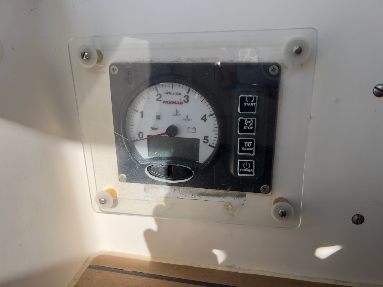
The ignition key socket in the original Yanmar engine display panel corroded. The engine hour meter was not working either. I had to order a new digital panel and a conversion kit. Yanmar finally replaced the ignition key with a button. Great! It would be even better if they included a means to protect the buttons from an accidental push; for example, make them recessed or cover them. I had to make and install the cover myself.
June 2023. New Caledonia. New engine blower
The Chinese blower didn't work too long. I had to replace it after 3 years. I was able to buy a blower with a smaller diameter than the old one. I didn't replace the duct. I just managed to fit the larger duct to a smaller blower. Not ideal but it worked. The new blower is slightly less powerful. It draws 3A instead of 5. Therefore, I turn it on for 10 minutes every hour during daytime. Slightly earlier I had to replace a WiFi relay.
November 2023. Reunion. Another Racor 230R fuel filter and a pump for transferring diesel from jerry cans to a fuel tank
I was able to find the Racor R230R fuel filter assembly in Reunion. I had a pump and a breaker installed in a cockpit locker earlier same year while staying on another French island, New Caledonia.
I also purchased a funnel with a filter for use at a pump station. When sailing, it is much easier to pump diesel from canisters into the tank rather than pouring it straight from the cans. Often a dirt and water come with diesel fuel and accumulate in cans. Using a filter seems like a good idea.
November 2023. On the way to Richards Bay from Reunion. New engine temperature sensor and display
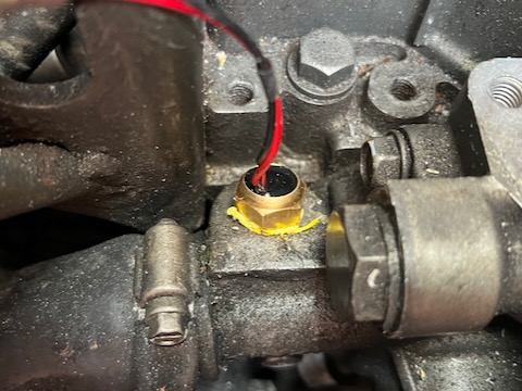
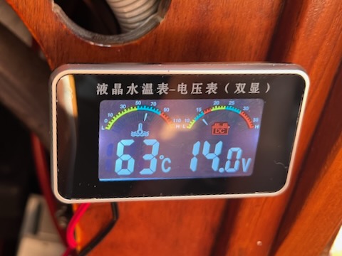
When I was approaching Richards Bay in South Africa, I had a problem with engine heating. The alarm sounded. I had purchased a digital temperature sensor with an LCD a few years ago. It was time to install it during this incident. Besides sounding an alarm, it shows an antifreeze mix temperature as a number of degrees in C.